top of page
  • Writer's pictureISNM

Additive manufacturing of polymer-derived ceramics

BY ZAK C. ECKEL, CHAOYIN ZHOU, JOHN H. MARTIN, ALAN J. JACOBSEN, WILLIAM B. CARTER, TOBIAS A. SCHAEDLER

SCIENCE01 JAN 2016 : 58-62

http://science.sciencemag.org/content/351/6268/58


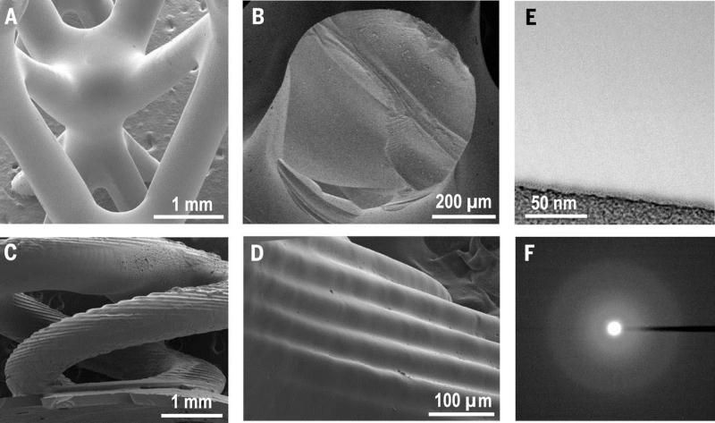
Preceramic monomers can be patterned, using stereolithography or 3D printing, into complex shapes and cellular architectures.


Abstract

The extremely high melting point of many ceramics adds challenges to additive manufacturing as compared with metals and polymers. Because ceramics cannot be cast or machined easily, three-dimensional (3D) printing enables a big leap in geometrical flexibility. We report preceramic monomers that are cured with ultraviolet light in a stereolithography 3D printer or through a patterned mask, forming 3D polymer structures that can have complex shape and cellular architecture. These polymer structures can be pyrolyzed to a ceramic with uniform shrinkage and virtually no porosity. Silicon oxycarbide microlattice and honeycomb cellular materials fabricated with this approach exhibit higher strength than ceramic foams of similar density. Additive manufacturing of such materials is of interest for propulsion components, thermal protection systems, porous burners, microelectromechanical systems, and electronic device packaging.

(A)	UV-curable preceramic monomers are mixed with photoinitiator. (B) The resin is exposed with UV light in a SLA 3D printer or through a patterned mask. (C) A preceramic polymer part is obtained. (D) Pyrolysis converts the polymer into a ceramic. Examples: (E) SLA 3D printed cork screw. (F and G) SPPW formed microlattices. (H) Honeycomb.
Fig. 1. Additive manufacturing of polymer-derived ceramics. (A) UV-curable preceramic monomers are mixed with photoinitiator. (B) The resin is exposed with UV light in a SLA 3D printer or through a patterned mask. (C) A preceramic polymer part is obtained. (D) Pyrolysis converts the polymer into a ceramic. Examples: (E) SLA 3D printed cork screw. (F and G) SPPW formed microlattices. (H) Honeycomb.

Fig. 2. Electron microscopy characterization of SiOC microlattice and cork screw. (A) SPPW-formed lattice node showing smooth surface. (B) Fracture surface of a strut. (C) SLA printed corkscrew showing undulations on the surface. (D) 3D printing step size is 50 μm. (E) Bright-field TEM image showing no porosity. (F) TEM diffraction indicating amorphous structure.

Fig. 3. Strength of polymer-derived SiOC materials compared to ceramic foams. (A) Compressive strength. (B) Shear strength.

Fig. 4. High-temperature oxidation of silicon oxycarbide microlattice. (A) Mass change measured after consecutive heat treatments at different temperatures normalized by surface area. (B) Mass change compared with other materials. [Data from (24–30)] (C) Fracture surface of a SiOC microlattice heat-treated 1300°C/10 hours + 1500°C/10 hours selected for extraction of (D) Focused ion beam lamella. (E) TEM image of the SiOC region. (F) TEM image of the SiO2 region.

5 views0 comments
bottom of page